15 April 2012

Scope Sunday 28

This morning, I am headed to the MIT Swapfest (the first one of the 2012 season!). I told my students to attend for extra credit (they have to find me and check in with me).

I'll update this post with photographs later today...


UPDATE: Ten students attended Swapfest! I have yet to get a full report on their purchases and finds, but I am encouraged that so many students attended on a holiday-weekend Sunday morning.

There were a few Tektronix oscilloscopes in attendance, but nothing that I didn't already have. Since it was the first Swapfest of the season, the prices were on the high side (next month, I'll have plenty of opportunities to buy stuff I don't need at NEAR-Fest, Dayton, and the May Swapfest). I did take a few pictures of some Tek gear.


A Tektronix RM31A. The guy wanted $100 for it. Good luck with that. The booth next to him had a 575 for sale, also for $100. The last time I bought a 575, I only paid $40 for it, and that was only because I wanted the property stickers.


Tektronix 453s and 454s for $40 each. That's a fair price for a working 454, but I already have too many.


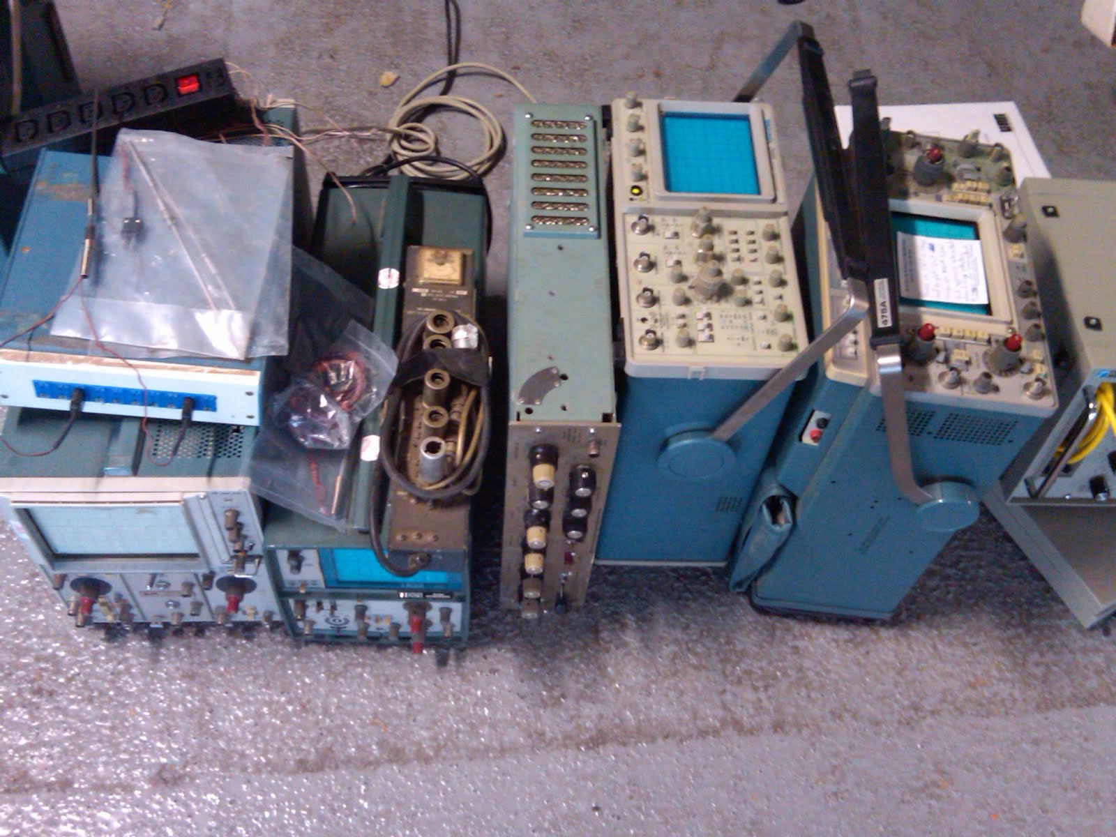
Other random oscilloscopes, for $60 each. Maybe there will be some better deals next month.


I did buy this book with an awesome cover. I couldn't resist!


Questions:

1. What's wrong with this dust jacket?

2. How mad do you think the author was when he saw what the art department did to the cover of his book?

12 April 2012

App Note 112

"Developments in battery stack voltage measurement: A simple solution to a not so simple problem." 24 pages.

In my last post, I retold my favorite Bob Widlar story, where he pulled a great misdirection prank in the literature right before the release of his landmark LM109 monolithic voltage regulator. I mentioned that story because an acquaintance of mine once suggested that App Note 112 was also a misdirection prank. He asserted that this battery-stack measurement scheme, using all of these transformers, switches, and diodes, is overcomplicated, and besides, Linear Technology later released the LTC6801 single-chip solution to battery-stack voltage measurement.

I don't believe that for a minute. Jim really did love transformers.

Jim once gave a talk to my M.I.T. class on "Transformers: Circuit Design's Hidden Ace," where he discussed the various and sundry measurement applications for transformers. He discussed this app note, as well as the Tektronix CT-1 and CT-2 current probes (see Figure 14 in App Note 106), low-voltage applications (see Figure 2 in App Note 113), and piezoelectric transformers (see App Note 81). He loved transformers. I bet that, even with the available single-chip solution with the LTC6801, Jim still thought that this transformer-based technique was best. No misdirection here.

(Also, this app note is reprinted in the third book as Chapter 19, which they wouldn't have done if it really was a prank.)

This app note discusses a transformer-based approach to measuring the individual cell voltages in a battery stack. The detailed schematic is shown in Figure 4, with the real accuracy shown in Figure 6. The transformer-caused droop on the DC measurement is only 0.2%. Figure 8a shows the multi-cell version, with both measurement channels and calibration channels (of course).

(Figure 8b and page 7 are where you can tell that this app note is coauthored.)

Appendix A is another great "A lot of cut off ears and no Van Goghs" appendix (like Appendix J in App Note 55). "The problem appears deceptively simple; technically and economically qualified solutions are notably elusive." Figure A2 is "quite expensive" indeed (the "low cost" AD202 isolation amplifiers are $30 each). Figure A3 is a switched capacitor scheme (which I suspect is the internal design of the previously mentioned LTC6801). Figure A4 uses many isolation barriers, of some kind.

Appendix B includes a "battery simulator" for testing. Appendix C ends the app note on a sour note (eight pages of microcontroller code).

The app note closes with a cartoon. "Piece of cake."

10 April 2012

My favorite Widlar story

My favorite Bob Widlar story is a huge misdirection prank that he pulled in the literature. In the late 1960s, many companies were designing IC voltage regulators, and there was a perceived demand for a monolithic device. Widlar convinced people that it couldn't be done, and then he did it.

In June 1969, he wrote a paper in EEE [1], where he laid out the case against monolithic voltage regulators. Using the (eight-pin) LM100 as an example, he convincingly argued three points, focusing on the detrimental effects of an integrated power transistor. In short, monolithic voltage regulators will never work because the die temperature will kill you, and if it didn't, then the temperature gradient would kill the reference, and even if it didn't, there's no way to package it (there weren't any standard high-power packages with enough pins). See page 93 of this article, under the heading "Power Limitations".

Case closed.

Then, in February 1970, he presented a paper at ISSCC [2], where he published the circuit of the LM109, the first monolithic voltage regulator. The solution, of course, was his bandgap voltage reference, which allowed the reference to coexist with the wide temperature swings caused by the integrated power transistor. Better yet, the whole thing fits into a three-terminal transistor package.

In February 1971, he published a paper in JSSC [3], which expands on the ISSCC paper. Given the various publication delays of these three publications, I imagine that these articles were submitted within days of each other.


[1] Robert J. Widlar, "Designing with positive voltage regulators," EEE, vol. 17, pp. 90–97, Jun. 1969.

[2] Robert J. Widlar, "New developments in IC voltage regulators," in IEEE International Solid-State Circuits Conference, Digest of Technical Papers, Feb. 1970, pp. 158–159.

[3] Robert J. Widlar, "New developments in IC voltage regulators," IEEE Journal of Solid-State Circuits, vol. 6, no. 1, pp. 2–7, Feb. 1971.


My second-favorite Widlar story is the one about the sheep.

08 April 2012

Scope Sunday 27

I bought my tickets and made reservations for the Dayton Hamvention in May. I'm flying in on Wednesday to do a few random things, but I'll definitely be at the flea market on Friday. Anyone else going?

Jim told me that he attended the flea market once. He spent the whole day just walking around and laughing at the sheer enormity of it.

Here are a few pictures that I took last time I was there (in 2010):


Tektronix 7000 mainframes, priced at $1 per pound, which is a good deal for a working 7904A, but a terrible deal for a broken 7704A. Choose wisely!


A couple of Tektronix 7854 mainframes. Nice.


The consummate boat anchor: a Tek 551 dual-beam (but single-time-base) oscilloscope with the external power supply. I'll keep my 556, thankyouverymuch.

04 April 2012

App Note 106

"Instrumentation circuitry using RMS-to-DC converters: RMS converters rectify average results." 20 pages.

This app note is a sad postscript to Jim's love of RMS-to-DC converters. One of Jim's favorite chips was the LT1088, which he originally discussed in App Note 22, and then used in many, many app notes, including App Notes 47, 49, 55, 61, 65, 75, and 83. Jim has heaped high praise upon these thermal RMS techniques. Appendix A in App Note 61 is particularly noteworthy, where he includes pictures and schematics of the innards of an HP3400A RMS voltmeter, and then compares it to the elegant simplicity of an LT1088 circuit.

However, the LT1088 is now obsolete. And with the present app note, it seems that it has been replaced by the LT1966 family, discussed here. There is no mention of thermal RMS techniques here, despite all of his previous rants and raves. (For example, see Figure C5 in App Note 83: "Four thermally based types agree within 1%. Other instruments show relative error as large as 48%.") If these parts were better than the LT1088 (and not just "newer"), wouldn't there be a direct comparison?

It gets worse... The only mention of thermally based RMS measurements appears in Appendix B, where he discusses laboratory meters by HP and Fluke. The footnote on page 17 says, "See references 1 and 2 for details on thermally based RMS-to-DC conversion" which are applications notes from Hewlett-Packard and Analog Devices. Why wouldn't he reference any of his own (voluminous) writing on thermal RMS-to-DC converters? Was he told to pretend that the LT1088 never existed?

Sad.

That all said, some of the applications circuits are quite interesting. Figure 8 is effectively a linear regulator that regulates an AC waveform (the MOSFET Q2 in the diode bridge is the series-pass element). Figures 9, 10, and 12 show high-fidelity preamplifiers. Figure 15 is an oscillator with frequency stabilization (using a quartz crystal) and amplitude stabilization (using an RMS measurement loop). Figure 17 is a RMS-leveled noise generator. Figure 20 is an AGC loop that uses the RMS measurement in the feedback path (see also Figure 139 in App Note 47).

The app note ends with a cartoon. "The Good, the Bad, and the Ugly."


I suppose that the LT1088 would have taken the crown as "the beautiful one".