18 June 2012

Bob Pease

One of my favorite pictures of Bob Pease is the one of him throwing a computer off the top of the National Semiconductor parking garage (page 145 in his book).  It's a great image of Bob as curmudgeon.


Since today is the anniversary of his tragic death, I decided to throw a computer off my roof in his memory.  I invite you to join me.


Two stories wasn't high enough.  The outer case popped off, and the hard-disk mount broke loose, but it didn't shatter into a million pieces.  Your mileage may vary.


UPDATE: Dino Segovis (@MakerDino on Twitter) posted an excellent video to YouTube, "Computer Toss in Memory of Bob Pease". He achieved much better results than I did, although the sledgehammer helped.

12 June 2012

14 April 1948 -- 12 June 2011

We miss you, Jim.


Observe a moment of silence today while the tubes in your scope warm up.

11 June 2012

Scope Sunday 31

This weekend I had some business in California (or more accurately, I scheduled some business in California for this weekend), so I was able to attend the Electronics Flea Market at De Anza College. I stayed in a nearby hotel and (being on east-coast time) got up at the crack of dawn to arrive a little after 5am.


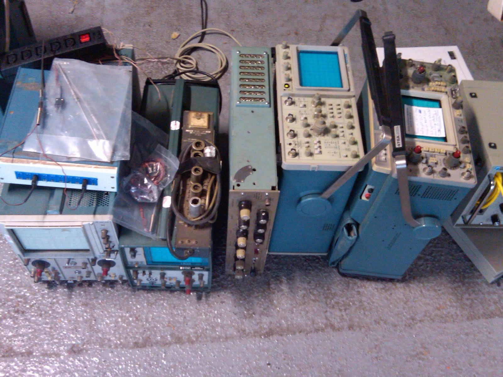
I've attended this flea market a dozen-or-so times, but I had never arrived so early before. I enjoyed the early-morning wandering around and watching the crowd flock from vendor to vendor as they rolled into the parking lot. (It was also the first time I've attended since they moved to the south side of the parking lot, underneath the solar panels. I confess that my heart sank when I came around the corner on Stevens Creek and saw that the north side of the parking lot was empty!) There was some good gear available, but much of it was priced too high. This table also had a Tektronix 475A for $200 and a 454 for $75. Nope.


One seller had a stack of 2465 scopes, but without a way to test them (and already having two carry-on bags for my flight home), it wasn't worth the risk. The 2465 is a nice scope if it works, and a terrible scope if it doesn't (it's basically unrepairable because of unobtainium custom parts). This seller also had two 7104 mainframes, but they were sold before I got to the space.


There was some other interesting and pretty gear there, but no large items that I really needed to buy.


This next item made me laugh out loud. "Connects 2 components instantly!" You know, as opposed to all those wires that connect things gradually.


Several items I wish I had bought, but was beaten to the punch before I made up my mind (little stuff, like a fat bag of 3904 transistors, a set of over-sized crystals, and a Boss OD-1). There was also a weird Tektronix 500-series plug-in module (it may have been a Type K) that had its faceplate sanded completely off. Curious. However, I did not come home empty-handed. in addition to a vacuum tube and a different set of crystals, I found a binder full of six years (1972 to 1977) of the TekScope application notes for $3. Very, very nice:


The best part of the flea market was running into some friends, both old and new. I saw Prof. Tom Lee there (who is supposed to be in Washington D.C., but also scheduled some West-Coast business for flea-market weekend), and I also met Jerry and Fran. However, I must admit that it really wasn't the same without Jim.

28 May 2012

Scope Sunday 30

Dayton was fun. The weather was beautiful. I spent Thursday at Fair Radio and the Air Force Museum. On Friday and Saturday at the Hamvention Flea Market, I saw lots of junque, met with some great people, and bought some stuff. The flea market seemed smaller than previous years (especially given the beautiful weather; it should have been crushed). A few of my friends noted some conspicuously missing vendors (like the dollar-per-pound "Hanger 18" people). Regardless, I believe that a good time was had by all.

I have several weeks' worth of stories to tell from Dayton, but I thought that I'd start with this quick one: My carry-on bag for the flight home was a Type Z plug in, packaged in a (musty-smelling) laptop bag that I also bought at the flea market.

The TSA agents at the airport didn't even blink. This experience mirrors the experience that I had in San Francisco with my carry-on 453 oscilloscope. However, I was nervous about the screening: two years ago, a Dayton TSA agent confiscated one ounce of toothpaste from my carry-on bag because it was in a six-ounce tube.

14 May 2012

Scope Sunday 29

I apologize for the lengthy absence, but end-of-term teaching obligations got the better of me. However, I have just submitted my final grades, and I'm looking forward to getting back to my "other" jobs. Here are a few updates from the last month that I have been remiss in contributing:

1. Last weekend, I attended NEAR-fest up in Deerfield, N.H. Unfortunately, the weather was not cooperative (cold and damp), and the turn-out was low. I didn't see any interesting gear there, and all I bought was a couple of books. Looking at my phone, I only took one picture while I was there (and it was for a friend, who was looking for a spectrum analyzer).
2. On the way home from NEAR-fest, I stopped by Electronic Surplus Services in Manchester, but I all found was a shelf of undesirable plug-ins (mostly 7A18 vertical amplifiers and slow time bases).

3. Also, last weekend, I hopped down to New Jersey and attended the Vintage Computer Festival East 8.0 at Camp Evans in Wall, N.J. I gave a talk on the history and legacy of analog computers. There were quite a few interesting computers on display in the exhibit hall, but only one Tektronix oscilloscope: a rack-mount RM503 that was connected to a PDP-8.

Another exhibit that caught my eye was a gentleman who had several boards from a Minuteman I flight computer. I recognized these boards because I has seen them on Jim Williams' living-room wall. (See the first three minutes of this video.)

However, tucked into corner of one of the exhibit rooms in the InfoAge Center and Museum was this poster, with a story about Howard Vollum that I had not heard before:

4. Next weekend is the Dayton Hamvention. Let me know if you're going; I hope to see you there.

15 April 2012

Scope Sunday 28

This morning, I am headed to the MIT Swapfest (the first one of the 2012 season!). I told my students to attend for extra credit (they have to find me and check in with me).

I'll update this post with photographs later today...


UPDATE: Ten students attended Swapfest! I have yet to get a full report on their purchases and finds, but I am encouraged that so many students attended on a holiday-weekend Sunday morning.

There were a few Tektronix oscilloscopes in attendance, but nothing that I didn't already have. Since it was the first Swapfest of the season, the prices were on the high side (next month, I'll have plenty of opportunities to buy stuff I don't need at NEAR-Fest, Dayton, and the May Swapfest). I did take a few pictures of some Tek gear.


A Tektronix RM31A. The guy wanted $100 for it. Good luck with that. The booth next to him had a 575 for sale, also for $100. The last time I bought a 575, I only paid $40 for it, and that was only because I wanted the property stickers.


Tektronix 453s and 454s for $40 each. That's a fair price for a working 454, but I already have too many.


Other random oscilloscopes, for $60 each. Maybe there will be some better deals next month.


I did buy this book with an awesome cover. I couldn't resist!


Questions:

1. What's wrong with this dust jacket?

2. How mad do you think the author was when he saw what the art department did to the cover of his book?

12 April 2012

App Note 112

"Developments in battery stack voltage measurement: A simple solution to a not so simple problem." 24 pages.

In my last post, I retold my favorite Bob Widlar story, where he pulled a great misdirection prank in the literature right before the release of his landmark LM109 monolithic voltage regulator. I mentioned that story because an acquaintance of mine once suggested that App Note 112 was also a misdirection prank. He asserted that this battery-stack measurement scheme, using all of these transformers, switches, and diodes, is overcomplicated, and besides, Linear Technology later released the LTC6801 single-chip solution to battery-stack voltage measurement.

I don't believe that for a minute. Jim really did love transformers.

Jim once gave a talk to my M.I.T. class on "Transformers: Circuit Design's Hidden Ace," where he discussed the various and sundry measurement applications for transformers. He discussed this app note, as well as the Tektronix CT-1 and CT-2 current probes (see Figure 14 in App Note 106), low-voltage applications (see Figure 2 in App Note 113), and piezoelectric transformers (see App Note 81). He loved transformers. I bet that, even with the available single-chip solution with the LTC6801, Jim still thought that this transformer-based technique was best. No misdirection here.

(Also, this app note is reprinted in the third book as Chapter 19, which they wouldn't have done if it really was a prank.)

This app note discusses a transformer-based approach to measuring the individual cell voltages in a battery stack. The detailed schematic is shown in Figure 4, with the real accuracy shown in Figure 6. The transformer-caused droop on the DC measurement is only 0.2%. Figure 8a shows the multi-cell version, with both measurement channels and calibration channels (of course).

(Figure 8b and page 7 are where you can tell that this app note is coauthored.)

Appendix A is another great "A lot of cut off ears and no Van Goghs" appendix (like Appendix J in App Note 55). "The problem appears deceptively simple; technically and economically qualified solutions are notably elusive." Figure A2 is "quite expensive" indeed (the "low cost" AD202 isolation amplifiers are $30 each). Figure A3 is a switched capacitor scheme (which I suspect is the internal design of the previously mentioned LTC6801). Figure A4 uses many isolation barriers, of some kind.

Appendix B includes a "battery simulator" for testing. Appendix C ends the app note on a sour note (eight pages of microcontroller code).

The app note closes with a cartoon. "Piece of cake."

10 April 2012

My favorite Widlar story

My favorite Bob Widlar story is a huge misdirection prank that he pulled in the literature. In the late 1960s, many companies were designing IC voltage regulators, and there was a perceived demand for a monolithic device. Widlar convinced people that it couldn't be done, and then he did it.

In June 1969, he wrote a paper in EEE [1], where he laid out the case against monolithic voltage regulators. Using the (eight-pin) LM100 as an example, he convincingly argued three points, focusing on the detrimental effects of an integrated power transistor. In short, monolithic voltage regulators will never work because the die temperature will kill you, and if it didn't, then the temperature gradient would kill the reference, and even if it didn't, there's no way to package it (there weren't any standard high-power packages with enough pins). See page 93 of this article, under the heading "Power Limitations".

Case closed.

Then, in February 1970, he presented a paper at ISSCC [2], where he published the circuit of the LM109, the first monolithic voltage regulator. The solution, of course, was his bandgap voltage reference, which allowed the reference to coexist with the wide temperature swings caused by the integrated power transistor. Better yet, the whole thing fits into a three-terminal transistor package.

In February 1971, he published a paper in JSSC [3], which expands on the ISSCC paper. Given the various publication delays of these three publications, I imagine that these articles were submitted within days of each other.


[1] Robert J. Widlar, "Designing with positive voltage regulators," EEE, vol. 17, pp. 90–97, Jun. 1969.

[2] Robert J. Widlar, "New developments in IC voltage regulators," in IEEE International Solid-State Circuits Conference, Digest of Technical Papers, Feb. 1970, pp. 158–159.

[3] Robert J. Widlar, "New developments in IC voltage regulators," IEEE Journal of Solid-State Circuits, vol. 6, no. 1, pp. 2–7, Feb. 1971.


My second-favorite Widlar story is the one about the sheep.

08 April 2012

Scope Sunday 27

I bought my tickets and made reservations for the Dayton Hamvention in May. I'm flying in on Wednesday to do a few random things, but I'll definitely be at the flea market on Friday. Anyone else going?

Jim told me that he attended the flea market once. He spent the whole day just walking around and laughing at the sheer enormity of it.

Here are a few pictures that I took last time I was there (in 2010):


Tektronix 7000 mainframes, priced at $1 per pound, which is a good deal for a working 7904A, but a terrible deal for a broken 7704A. Choose wisely!


A couple of Tektronix 7854 mainframes. Nice.


The consummate boat anchor: a Tek 551 dual-beam (but single-time-base) oscilloscope with the external power supply. I'll keep my 556, thankyouverymuch.

04 April 2012

App Note 106

"Instrumentation circuitry using RMS-to-DC converters: RMS converters rectify average results." 20 pages.

This app note is a sad postscript to Jim's love of RMS-to-DC converters. One of Jim's favorite chips was the LT1088, which he originally discussed in App Note 22, and then used in many, many app notes, including App Notes 47, 49, 55, 61, 65, 75, and 83. Jim has heaped high praise upon these thermal RMS techniques. Appendix A in App Note 61 is particularly noteworthy, where he includes pictures and schematics of the innards of an HP3400A RMS voltmeter, and then compares it to the elegant simplicity of an LT1088 circuit.

However, the LT1088 is now obsolete. And with the present app note, it seems that it has been replaced by the LT1966 family, discussed here. There is no mention of thermal RMS techniques here, despite all of his previous rants and raves. (For example, see Figure C5 in App Note 83: "Four thermally based types agree within 1%. Other instruments show relative error as large as 48%.") If these parts were better than the LT1088 (and not just "newer"), wouldn't there be a direct comparison?

It gets worse... The only mention of thermally based RMS measurements appears in Appendix B, where he discusses laboratory meters by HP and Fluke. The footnote on page 17 says, "See references 1 and 2 for details on thermally based RMS-to-DC conversion" which are applications notes from Hewlett-Packard and Analog Devices. Why wouldn't he reference any of his own (voluminous) writing on thermal RMS-to-DC converters? Was he told to pretend that the LT1088 never existed?

Sad.

That all said, some of the applications circuits are quite interesting. Figure 8 is effectively a linear regulator that regulates an AC waveform (the MOSFET Q2 in the diode bridge is the series-pass element). Figures 9, 10, and 12 show high-fidelity preamplifiers. Figure 15 is an oscillator with frequency stabilization (using a quartz crystal) and amplitude stabilization (using an RMS measurement loop). Figure 17 is a RMS-leveled noise generator. Figure 20 is an AGC loop that uses the RMS measurement in the feedback path (see also Figure 139 in App Note 47).

The app note ends with a cartoon. "The Good, the Bad, and the Ugly."


I suppose that the LT1088 would have taken the crown as "the beautiful one".

25 March 2012

Scope Sunday 26

I finally(*) got a chance to fire up the Tektronix 566 that I purchased before Christmas. Here it is with eight independent traces on the screen (using two 1A4 four-channel plug-ins and independent time bases). It works like a champ. Now, as soon as I can get my 1L5 repaired, I'll be proudly replicating Figure 34 in App Note 35.


(*) Actually, I fired it up several weeks ago, but I didn't get a very good picture of it then.

09 March 2012

App Note 104

Load transient response testing for voltage regulators: Practical considerations for testing and evaluating results. 16 pages.

This app note discusses testing linear regulators under varying loads. Most of the circuitry in this app note is geared toward producing fast and large current pulses, like those shown in Figure 4. The main idea is shown in Figure 2; by turning the transistor Q1 on and off, the "regulator under test" can be put through its paces.

The next circuits allow for a continuously varying load level (instead of the discrete levels produced by the circuit in Figure 2). Figure 6 is implemented with a MOSFET device, while Figure 8 uses a BJT. The main trade-off is in the number of circuit trims; due to the large gate capacitance of the IRLZ24, the loop dynamics are (apparently) harder to tame.

The rest of the app note shows a number of measurements made with this test circuit. Figure 15 is particularly pretty, showing a swept-sine input from DC to 5MHz, which clearly shows the frequency range of the LT1963A's load rejection. Figure 16 starts a discussion on the effects of parasitics in the output capacitor. Sage advice appears in footnote 4, "Always specify components according to observed performance, never to salesman’s claims." This point is re-enforced by the presence of the 100-mV spike in Figure 30, due to a "poor grade 10uF" capacitor.

Appendices A (capacitor parasitics) and B (load regulation from the LT1963A datasheet) were guest-written by Tony Bonte and Dennis O'Neill, respectively.

Appendix C discusses proper probing and cabling techniques for these measurement. Due to the wide-band nature of the transients, attention to detail is required.
The termination at the oscilloscope end is not negotiable.
Appendix D shows an improvement to Figure 8, which doesn't require as many manual trims.

The app note ends with a cartoon. "Methinks the load doth protest too much (with apologies to Wm. Shakespeare)."

07 March 2012

App Note 101

"Minimizing switching regulator residue in linear regulator outputs: Banishing those accursed spikes." 12 pages.

This short app note discusses the use of linear regulators to "clean up" the unavoidable ripple and spikes that exist in the outputs from switching regulators (see Figure 2). As Jim describes,
In practice, all linear regulators encounter some difficulty with ripple and spikes, particularly as frequency rises... Large numbers of capacitors and aspirin have been expended in attempts to eliminate these undesired signals and their resultant effects.
Much of the app note addresses the measurement of ripple-and-spike rejection of various linear regulators (of course), so Figure 5 shows a ripple-and-spike simulator. This circuit produces controllable input ripple and spikes to the regulator under test. Figures 7 through 13 show the results of such measurements.

Appendix A sings the praises of ferrite beads and Appendix B discusses the limitations of using inductors instead of ferrite beads. Appendix C discusses wide-band submillivolt measurements.

Best quote (from footnote 2, discussing the reduction in spike amplitude achieved with an appropriately placed ferrite bead): "Dramatic" is perhaps a theatrical descriptive, but certain types find drama in these things.

The app note ends with a cartoon that praises ferrite beads. "Megahurts to minihurts converter."

02 March 2012

App Note 98 part 2

Figure 37 is a highly linear voltage-to-frequency converter, based on a quartz-stabilized switched-current charge loop. Q=IT (see App Note 14). The 0 to 10-kHz range exhibits 0.0015% linearity. I surprised that the LTC1043 is that good as a current switch (since it is designed as a good voltage switch).

The rest of the circuits are power converters, covering a wide range of applications, most of them high-voltage regulators based on circuits from previous app notes.

Figure 40 is an LT3468 flashlamp circuit, simplified by removing the red-eye-reduction capability (see App Note 95). Figure 44 reuses the LT3468 flashlamp controller to implement a 0 to 300-V variable supply. Figure 46 improves the output-ripple voltage by including a discrete-linear-regulator design on the output (see App Note 32). Figure 48 is a 5V-to-200V switching regulator for APD biasing (see App Note 92). Figure 50 is a wide-range regulator that provides 0 to 500 volts at 100 watts of output power (see App Note 35).

The final circuit, in Figure 55, isn't a high-voltage circuit, but instead is a load-sharing scheme between two low-voltage linear regulators.

Appendix A briefly discusses bandwidth and rise time for high-speed measurements, and Appendix B discusses connectors, cables, adapters, attenuators, and probes for high-speed measurements.

The app note concludes with a cartoon. "It's dark in there. You can think about circuits."

29 February 2012

App Note 98 part 1

Signal sources, conditioners and power circuitry: Circuits of the fall, 2004. 28 pages.

This app note is another circuits collection of more-or-less random projects, as he has previously done in App Note 45, App Note 61, and App Note 75.

The app note starts with a simple implementation of a current source in Figure 1. The real application circuit in Figure 2, produces "alternating, equal amplitude, opposed polarity linear capacitor ramps". An interesting choice for the output waveform: I wonder what this signal was used for?

Figure 4 shows a simple sine-wave oscillator (well, really a heavily filtered triangle-wave oscillator). I think the interesting piece of this circuit is the use of the one-sided output from the single-supply A3 to implement half-wave rectification in the amplitude-control loop. Cheesy, but clever.

Figure 6 shows a wide-band high-voltage level shifter, capable of producing 50-volt pulses without overshoot. The footnote exposes a brave design choice:
Transistor data sheet aficionados may notice that the –50V potential exceeds Q1, Q2, Q3 VCEO specifications. The transistors operate under VCER conditions, where breakdown is considerably higher.

The next few circuits include several different pulse generators. He seems to be exploring a wide array of alternatives to his usual avalanche-based pulsers (such as Appendix B in App Note 79). Figure 8 uses a single-chip oscillator that achieves a 400-ps rise time (as shown in Figure 10) and a 320-ps fall time (Figure 11). Nice and simple. Figure 12, inspired by the calibrator circuit from the Tektronix 485 oscilloscope, produces a 850-ps rise time, with a flat-top pulse. Clean and pretty. Figure 15 uses a unique (and discontinued) HP tunnel diode to produce a 20-ps (twenty! picoseconds!) rise time. Yikes. Figure 19 produces pulses with controlled widths, down to 1 ns.

The next three circuits are instrumentation applications. Figure 25 shows a single-supply amplifier, which uses the chopper-clock output to drive a charge pump to allow true-zero-volt output swing. This circuit is them used in the milliohmmeter in Figure 27 and the instrumentation amplifier in Figure 30.

Figure 32 show a wide-band low-feedthrough switch using transconductance amplifiers, developed for settling time measurement (we'll see this circuit again in App Note 120).

I'll cover the rest of the circuits next time.

26 February 2012

Vintage scopes are better part 4

Vintage scopes are better (also see part one, part two, and part three).

Reason number 4: Repairabililty and inspiration.

It is nearly impossible to get a useful service manual for a modern oscilloscope, and even if you could, the parts to repair it are generally unobtainable custom ICs. However, many vintage scopes are repairable, and complete service manuals are readily available for many models. While some vintage parts are getting hard to find (cough, tunnel diodes, cough), many repairs are possible with easily obtained parts. In his second book, Jim explains,
Older equipment offers another subtle economic advantage. It is far easier to repair than modern instruments. Discrete circuitry and standard-product ICs ease servicing and parts replacement problems. Contemporary processor-driven instruments are difficult to fix because their software control is "invisible", often convoluted, and almost impervious to standard troubleshooting techniques. Accurate diagnosis based on symptoms is extremely difficult... Additionally, the widespread usage of custom ICs presents a formidable barrier to home repair. [1]
In addition, vintage scopes are extremely well-designed and well-constructed. Much can be learned from examining and exploring the internals of classic oscilloscope.
The inside of a broken, but well-designed piece of test equipment is an extraordinarily effective classroom... The clever, elegant, and often interdisciplinary approaches found in many instruments are eye-opening, and frequently directly applicable to your own design work. More importantly, they force self-examination, hopefully preventing rote approaches to problem solving... The specific circuit tricks you see are certainly adaptable and useful, but not nearly as valuable as studying the thought process that produced them. [2]
His love of vintage scopes was a continual source of inspiration. He studied, referred to, and borrowed extensively from classic instruments and their service manuals. For example,
  • The high-speed ECL logic in the "King Kong V/F" in App Note 14 was inspired by the trigger circuitry of the Tektronix 2235.
  • The adaptive threshold trigger circuit in Figure 130 of App Note 47 was also inspired by the Tektronix 2235.
  • In his discussion of CCFL power supplies in [3], Jim explored the high-voltage resonant power supplies in the Tektronix 547 and the Tektronix 453.
  • In his discussion of low-noise power conversion (App Note 70, Appendix A), he discusses circuits from the Tektronix 454 and 7904 (Figures A1 and A2).
  • Figure 12 in App Note 98 was derived from the calibrator circuit in a Tektronix 485.

References:

[1] Jim Williams, "There's no place like home," in The Art and Science of Analog Circuit Design, Jim Williams, Ed. Boston: Butterworth-Heinemann, 1995, ch. 17, pp. 269–277.

[2] Jim Williams, "The importance of fixing," in The Art and Science of Analog Circuit Design, Jim Williams, Ed. Boston: Butterworth-Heinemann, 1995, ch. 1, pp. 3–7.

[3] Jim Williams, "Tripping the light fantastic," in The Art and Science of Analog Circuit Design, Jim Williams, Ed. Boston: Butterworth-Heinemann, 1995, ch. 11, pp. 139–193.

22 February 2012

App Note 95

Simple circuitry for cellular telephone/camera flash illumination: A practical guide for successfully implementing flashlamps. 12 pages.

This short little app note with a long title discusses the LT3468, which is a monolithic power-converter chip for driving camera flashtubes. As Figure 1 testifies, flashlamps are much brighter with better color temperature than LEDs, and so are the preferred illuminator for digital cameras. After a brief discussion of the physics, Jim discusses the support circuitry and construction requirements. "Capacitor, wiring and lamp impedances typically total a few ohms, resulting in transient current flow in the 100A range."

This app note contains a single application schematic, shown in Figure 6. Most of the text is dedicated to measurements of the circuit performance (Figures 7 to 10). Figures 9 and 10 are particularly interesting, with vertical scales of "relative light per division". Surprisingly, Jim does not reveal how he made the "relative light" measurements.

A carefully worded caution appears near the end of the text:
In cases where the lamp is triggered with a user-selected transformer and drive scheme, it is essential to obtain lamp vendor approval before going to production.
That quote sounds like the voice of unfortunate experience.

The app note ends with a cartoon. "Nice seeing you again. Yeah, nice seeing you again, too."

19 February 2012

Vintage scopes are better part 3

Vintage scopes are better. (See part one and part two.)

Reason 3: Overdrive resilience.

Several of Jim's App Notes were concerned with the measurement of settling time (for examples, see App Notes 120, 86, 79, 74, 47, and 10). In App Note 79, he measures the 0.1%-settling time of a high-speed op amp (5-millivolt settling on a 5-volt step). In App Note 120, he attempts to measure the LSB-settling time of a 20-bit DAC (10-microvolt settling on a 10-volt step). In these kinds of measurements, the primary concern is avoiding overdrive in the oscilloscope. An input-gain setting that allows the user to see 5-mV-settling details also allows the 5-V waveform to travel off the screen (and overload the vertical amplifier).

In Appendix B of App Note 120, he explains the problem,
Oscilloscope recovery from overdrive is a murky area and almost never specified. How long must one wait after an overdrive before the display can be taken seriously? (App Note 120, page 14)
The horrors of overdrive are readily apparent on page 16.


The waveform looks fine in Figures B2 to B4, but when part of the transient is off the screen, as in Figures B5 to B7, the oscilloscope is clearly having trouble. "It is obvious that for this particular waveform, accurate results cannot be obtained at this gain."

However, in this application, vintage scopes are better. Specifically, the classical sampling oscilloscope is immune to overdrive. To explain, Jim compares the architecture of and analog scope, a digital scope, and a classical sampling scope, all shown in Figure B1.


Describing the advantages of the classical sampling scope, he explains,
The classical sampling oscilloscope is unique. Its nature of operation makes it inherently immune to overload. Figure B1C shows why. The sampling occurs before any gain is taken in the system. Unlike Figure B1B’s digitally sampled ‘scope, the input is fully passive to the sampling point. Additionally, the output is fed back to the sampling bridge, maintaining its operating point over a very wide range of inputs. The dynamic swing available to maintain the bridge output is large and easily accommodates a wide range of oscilloscope inputs. Because of all this, the amplifiers in this instrument do not see overload, even at 1000x overdrives, and there is no recovery problem. Additional immunity derives from the instrument’s relatively slow sample rate—even if the amplifiers were overloaded, they would have plenty of time to recover between samples. (App Note 120, page 14)

A final word from Jim, "Unfortunately, classical sampling oscilloscopes are no longer manufactured, so if you have one, take care of it!"

17 February 2012

App Note 94

Slew rate verification for wideband amplifiers: The taming of the slew. 12 pages.

This app note discusses slew-rate measurement, which is another great application for Jim's high-speed pulse generators. The text is only 12 pages long, but it is not a "brief" project. Previously, he has used a variety of pulse generators for measuring oscilloscope bandwidth and amplifier settling times. For examples of the circuits used in some of these other applications, see
Here he is directly measuring slew rate, which requires even faster pulse rise times.

The app note begins with a quick history lesson in footnote 2,
The term "slew rate" has a clouded origin. Although used for many years in amplifier literature, there is no mention of it on the Philbrick K2-W (the first standard product op amp, introduced in January 1953) data sheet, dated 1964. Rather, the somewhat more dignified "maximum rate of output swing" is specified.
He quickly gets to the heart of the matter, the discussion of the necessary subnanosecond-rise-time pulse generator. The schematic in Figure 8 shows his 360-ps design, which is a great piece of work. This design is an improved version of Figure B1 in App Note 79.

Although the complete schematic is shown, a picture of the actual construction is missing. Much of the "secret sauce" of high-speed pulse generation is in the construction technique (as alluded to in footnote 11), so it is unfortunate that a photoessay isn't included. (I've seen one of these boxes, and it makes Figure B3 in App Note 72 look like child's play.)

Figures 11 to 17 show the calibration of pulse damping, the 360-ps rise time, and the measurement of the LT1818 slew rate. Several of these figures (such as 11, 12, 13, 16, and 18) were made with his Tektronix 7104 with 7A29 and 7B15 plug-ins that he discusses on page 4. These figures are the first appearance of his 7104 (note the legend in Figure 2). I discussed this marvelous scope in a previous post.

Appendix A discusses measurement integrity, using a time-mark generator (Figure A1) and a 20-ps rise-time pulse generator (see the table in Figure A3). Yes, Figure A4 is produced by a pulse with a twenty-picosecond rise time! Appendix B discusses level-shifting (no active circuits here; your only hope is to use excellent transformers).

Appendix C discusses the horrors of connectors, cables, adapters, attenuators, and probes at these high speeds. The best quote is on page 11:
Skepticism, tempered by enlightenment, is a useful tool when constructing a signal path and no amount of hope is as effective as preparation and directed experimentation.
The cartoon shows off his 7104 scope, with a 7M13 alphanumeric readout plug-in (which produced his "signature" WILLIAMS03 in the corner). "I'm going as fast as I can."

12 February 2012

Vintage scopes are better part 2

Vintage scopes are better. (See the introduction in part one.)

Reason number 2: Sensitivity and bandwidth. With the appropriate plug-ins, analog oscilloscopes provide superior sensitivity compared to digital scopes. In discussing low-level noise measurements in App Note 70, Jim describes the oscilloscope requirements and laments,
Current generation oscilloscopes rarely have greater than 2mV/DIV sensitivity, although older instruments offer more capability. Figure B11 lists representative preamplifiers and oscilloscope plug-ins suitable for noise measurement. These units feature wideband, low noise performance. It is particularly significant that the majority of these instruments are no longer produced. This is in keeping with current instrumentation trends, which emphasize digital signal acquisition as opposed to analog measurement capability. (App Note 70, page 29)
While 2 millivolts-per-division is commonplace in digital oscilloscopes, plug-ins are available for 500-series and 7000-series scopes with sensitivity down to 10 microvolts-per-division. Yes, microvolts. In Appendix D of App Note 124, Jim lists the high-sensitivity, low-noise amplifiers of choice.


Of course, sensitivity and bandwidth are related (the wider the bandwidth, the higher the expected noise floor). However, in conjunction with superior noise floor, some vintage analog scopes also provide very large bandwidths. Some of Jim's favorites were
  • Tektronix 556 with a 1S1 sampling plug-in, 1-GHz bandwidth (App Note 72, page 9, Figures 16 and 17)
  • Tektronix 547 with a 1S2 sampling plug-in, 3.9-GHz bandwidth (App Note 79, page 19, Figure B4)
  • Tektronix 661 with a 4S2 sampling plug-in, 3.9-GHz bandwidth (App Note 72, pages 34 and 35, Figure 77 to 82)
  • Tektronix 7104 with 7A29 and 7B15 plug-ins, 1-GHz real-time bandwidth (App Note 94, page 4, particularly Figures 2, 11, 12, 13, 16, and 18)
There are modern digital scopes available today with wider bandwidths, but "vintage" and "analog" does not mean "slow." Of course, Jim would want me to point out that bandwidth isn't everything. In App Note 47, he explained,
Intimate familiarity with your oscilloscope is invaluable in getting the best possible results with it. In fact, it is possible to use seemingly inadequate equipment to get good results if the equipment’s limitations are well known and respected. All of the circuits in the Applications section involve rise times and delays well above the 100MHz-200MHz region, but 90% of the development work was done with a 50MHz oscilloscope. Familiarity with equipment and thoughtful measurement technique permit useful measurements seemingly beyond instrument specifications. A 50MHz oscilloscope cannot track a 5ns rise time pulse, but it can measure a 2ns delay between two such events. Using such techniques, it is often possible to deduce the desired information. (App Note 47, page 20)
To be honest, the first sentence of that quote applies no matter what oscilloscope you have.


Footnote: One last comment while we're discussing plug-in oscilloscopes. The Tektronix 556 dual-beam instrument provides flexibility that is not found in modern instruments.
The Tektronix 556 offers an extraordinary array of features valuables in converter work. This dual beam instrument is essentially two full independent oscilloscopes sharing a single CRT. Independent vertical, horizontal and triggering permit detailed display of almost any converters operation. Equipped with two type 1A4 plug-ins, the 556 will display eight real time inputs. The independent triggering and time bases allow stable display of asynchronous events. Cross beam triggering is also available, and the CRT has exceptional trace clarity. (App Note 29, pages 43-44)
In App Note 65, he exploited these dual-beam advantages in a number of measurement. Figure 36 shows six waveforms, with independent triggering of the top two versus the bottom four traces. Figure 42 shows the ringing bursts at the resonant frequency of the Royer converter, with the explanatory footnote
The discontinuous energy delivery to the loop causes substantial jitter in the burst repetition rate, although the high voltage section maintains resonance. Unfortunately, circuit operation is in the "chop" mode region of most oscilloscopes, precluding a detailed display. "Alternate" mode operation causes waveform phasing errors, producing an inaccurate display. As such, waveform observation requires special techniques. Figure 42 was taken with a dual-beam instrument (Tektronix 556) with both beams slaved to one time base. Single sweep triggering eliminated jitter artifacts. Most oscilloscopes, whether analog or digital, will have trouble reproducing this display. (App Note 65, page 38)
Finally, the flexibility of the Tektronix 556 allows for some great measurement displays. In Figure 34 of App Note 35, he showed a 115-volt sine wave, its distortion products, and its frequency spectrum all in one shot.


In the accompanying footnote, Jim teased,
Test equipment aficionados may wish to consider how this picture was taken. Hint: Double exposure techniques were not used. This photograph is a real time, simultaneous display of frequency and time domain information. (App Note 35, page 16)
This picture was (most probably) produced with his trusty Tektronix 556 with a vertical-amplifier plug-in in one bay (perhaps a 1A2 or 1A4), and a spectrum-analyzer plug-in in the other bay (perhaps the 1L5 50Hz-to-1MHz spectrum analyzer).